A. Install Stop Sensors Into Track
Tools Required: Drill with 1/4 Inch Bit, pencil or tape,
Steps:
- Mark a line with pencil or tape across track at designated finish line
- Drill a 1/4 Inch hole in center of each lane. Note: BestTrack can provide this hole Pre-drilled.
- Insert stop sensor into each hole from bottom side of the track. Push each sensor up so that it extends about 1/4 Inch above the track surface.
- Lane 1 is Orange Wire
- Lane 2 is Green Wire
- Lane 3 is Blue Wire
- Lane 4 is Brown Wire
- Leave about 8-10 Inches of Stop Sensor cable extending beyond edge of track so that the RJ-45 connector can plug into TwinTurbo once the Display is installed.
- Once complete, push the sensors down into the hole to be flush with track surface. They can be tape in place or lightly glued if desired.
B. Mount TwinTurbo Display to Track
Tools Required: Drill with 5/32 Inch Bit, 5/32" Allen Wrench, Pencil or Sharpie, Phillips Screw Driver, Level (optional)
Steps:
- Set the TwinTurbo in place with each T-Slot Post touching the side rails of the BestTrack lanes. Fine tune the position so that the TwinTurbo is aligned straight across the track with the IR emitters facing down in line with the Stop Sensors in the track surface.
- Using pencil or Sharpie, mark the drill locations where the two Angled aluminum supports will mount to the track.
- Remove the TwinTurbo and set aside. Then drill 5/32 inch holes where marked in Step 2.
- Loosen the T-Slot screws a few turns to remove the Angled Aluminum brackets from the T-Slot Posts.
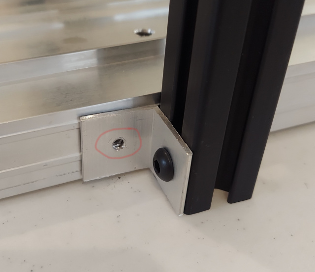
- Using the #10 Self-Tapping screws mount each bracket to the track, as shown in picture below.
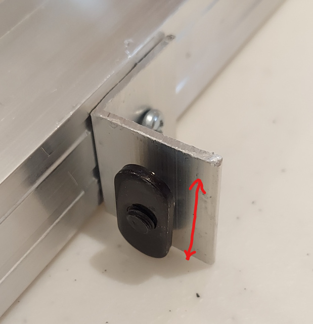
- Turn each T-Slot nut so that the long edge is vertical as shown in the picture above.
- Slide the TwinTurbo over each T-Slot nut, then using the 5/32" Allen Wrench, Tighten the two T-Slot screws. Adjust for vertical alignment of the T-Slot Posts if necessary and also adjust for level if needed. Use eye judgement or level if desired.
C. Install Start Switch
Tools Required: Drill with 3/32 Inch Bit, Small Phillips screw driver.
Steps:
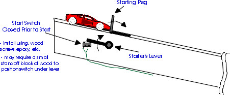
- Depending on the Start Lever implementation you may use the supplied 2-56 machine screws to mount the Start Switch with placement as shown in picture below. The 2-56 screws require a 3/32 inch hole size.
- The Start Switch should be installed so that the switch is held closed when the Starting Peg is up, blocking the cars from starting. The Switch should open when the lever is moved to start the race.
D. Connect Cables
- Run cable from Start Switch down to finish line and plug into the TwinTurbo where labelled.
- Connect the Stop Sensor cable (RJ45) into the TwinTurbo until it snaps in place.
- If a PC will be connected, connect the USB cable from TwinTurbo to PC.
- When ready, Plug in the 12V Power cable to TwinTurbo to Initiate the timer startup sequence.